Many USB wireless adapters have very good electronics paired with rather poor antennas. While these devices are adequate for very local networking, they are capable of much better performance when connected to a high quality external antenna. The Belkin F5D7050 is commonly available yet can give uncommon range and speed performance with the modification described here.
Here is a project that can greatly increase wifi connection speed and range. It can be applied to just about any commonly available adapter; one simply cuts out the built in antenna and runs a feedline to a high gain replacement. I have seen throughput on a 30 meter path go from 5.5 MB/Sec to a solid 54 MB/Sec – with reduced interference and no need for amplification. Note that longer path lengths (more than 200 meters or through walls and vegetation) may require making this modification to a device higher powered than the F5D7050.
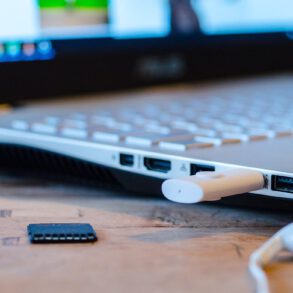
First, look at the circuit board. It boasts an efficient and clean layout. Data passes through the USB port on the left, and the antenna is etched on the right side. This modification is not difficult, but bright lighting and use of a magnifier is suggested due to the small surface mount parts and thin circuit traces on the adapter. It is a small work area, so use caution.
Tools Needed:
- An X-Acto Knife or razor for cutting traces and trimming coaxial cable.
- Soldering iron, with the tip sharpend, cleaned, and tinned.
- One coaxial “pigtail” with conectors apropriate for antenna to be used.
- Safety wire or epoxy for securing the pigtail to the PC board.
- Small drill if safety wiring will be used to secure the pigtail.
F5D7050 Modification Procedure:
- Carefully pry open the adapter and remove it from its enclosure. Plan to work on the area to the right of the shielded circuitry.
- Cut the printed circuit feedline between C11 and C152.
- If wire will be used to hold down the pigtail, drill four small (1mm dia) holes in a square adjacent to the internal patch antenna.
- Scrape away the coating over the ground plane in the area near C11 and D2.
- Carefully prepare one end of the coaxial feedline for soldering to the board (keep it neat and avoid long leads).
- Connect the center conductor to C11; solder the shield to the ground plane.
- Wire or glue the pigtail to the circuit board. Make sure it will not flex or rip loose.
- Carefully cut a gap into the enclosure to accomodate the pigtail, then re-enclose the circuit.
- Connect the adapter to the antenna; the modification is complete.
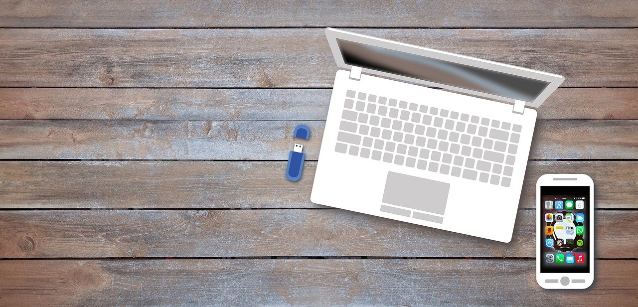
Above is an example of the modified F5D7050 and external antenna in operation. Some aiming will be necessary to peak the signal and maximize data rates. Performance of this USB wi fi adapter went from good to outstanding with the added external antenna.